
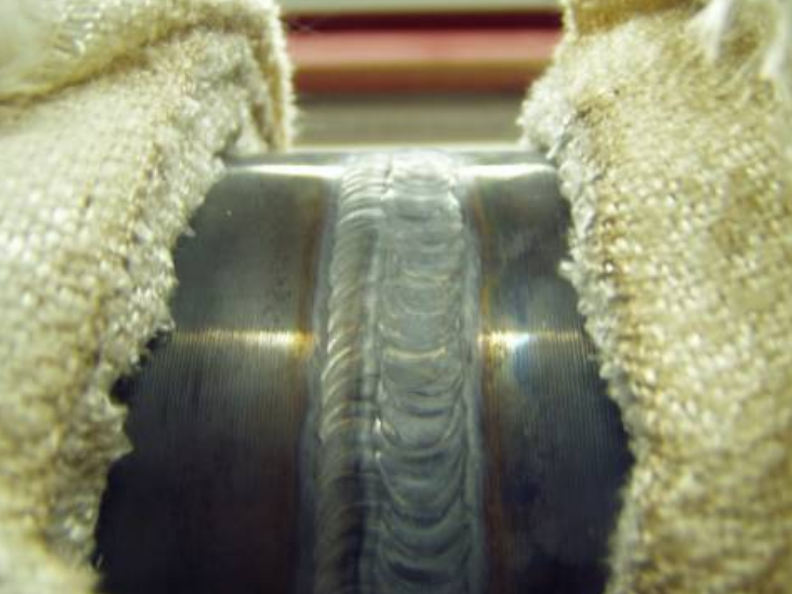

The Hollomon–Jaffe parameter is widely used to compare the metallurgical severity of tempering, post-weld heat treatment and other elevated-temperature exposures. In industrial practice, however, the calculation is often reduced to the nominal holding temperature and holding time. This simplification may be acceptable for long, well-controlled isothermal treatments, but it does not represent the complete thermal exposure of a component.
A thick-walled pressure component may be tempered by the steel manufacturer, subjected to one or more intermediate heat treatments during forming and fabrication, and then receives a further PWHT after repair during a turnaround 15 years later. The same issue is particularly relevant to CrMo and creep-resistant alloy components, such as heavy-section valve bodies, forgings and castings, where several thermal cycles may be applied before the equipment even enters service.
Each cycle adds to the cumulative metallurgical exposure. A material may fully comply with its specification in the original delivery condition, yet the combined effect of tempering, fabrication PWHT and repair heat treatments may reduce the remaining margin in strength, hardness, toughness or creep-related properties. This becomes especially important when procurement specifications define a maximum permissible Hp value, when simulated heat-treated test coupons are required, or when a welding procedure qualification does not realistically reproduce the full anticipated manufacturing heat-treatment history.
The same concern continues throughout the equipment lifecycle. Repair welding, local PWHT, and repeated maintenance interventions introduce further thermal exposure, often years after the original material qualification and fabrication records were issued. At that point, the question is no longer only whether the latest PWHT complied with the applicable code. The more important integrity question is whether the cumulative heat-treatment history remains compatible with the material properties assumed in the original design and subsequent fitness-for-service assessments.
This article explains the conventional Hollomon–Jaffe relationship, cumulative treatment of consecutive cycles and the engineering significance of heating and cooling contributions. It also discusses the limits of equivalent time–temperature calculations and the distinction between an Hp assessment, a complete heat-treatment simulation and construction-code compliance.
Keywords: Hollomon–Jaffe parameter, tempering, PWHT, stress relieving, cumulative heat treatment, equivalent time, Grade 91, ASME B31.1, EN 13445, EN 13480
Why cumulative heat-treatment exposure is so often overlooked
The Hollomon–Jaffe parameter frequently becomes a hidden source of problems during material procurement, fabrication planning and the review of welding procedure qualifications.
In many projects, attention is focused on one isolated heat-treatment stage: the tempering condition shown on the material certificate, the PWHT applied to a procedure qualification test, or the final stress-relieving cycle performed after fabrication. The material, however, does not experience these cycles independently.
A thick-walled pressure component may be normalized and tempered by the steel manufacturer, reheated during forming, subjected to intermediate stress relieving and then receive one or more final PWHT cycles after welding. Heavy-section CrMo forgings, castings and valve bodies may undergo several heat treatments before the equipment even enters service.
Each of these exposures becomes part of the material’s cumulative metallurgical history. The Hollomon–Jaffe method was originally developed to relate tempering time and temperature to the resulting degree of tempering, using hardness as the principal measurable response [1]. Subsequent reviews have shown that the concept remains highly useful, provided that its empirical nature and application limits are understood [2],[3].
The same issue continues during operation. Repair welding, local PWHT and repeated maintenance interventions can introduce additional thermal exposure years after the original fabrication records were issued.
The engineering question is therefore not only:
The broader integrity question is:
Defintion of the Hollomon-Jaffe parameter
The conventional relationship is commonly written as:
where:
- ⟦fx⟧ is the absolute temperature in Kelvin;
- ⟦fx⟧ is the exposure time in hours;
- ⟦fx⟧ is an empirical correlation constant;
- ⟦fx⟧ is the base-10 logarithm.
For practical pressure-equipment and PWHT calculations, a scaled form is frequently used:
The division by 1000 does not change the underlying relationship; it only converts values in the range of approximately 15000-22000 into more convenient values such as 15-22.
The parameter is convention-dependent. Every calculation report should therefore identify:
- the equation used;
- the temperature and time units;
- the selected value of ⟦fx⟧;
- whether the result is divided by 1000;
- the material-property correlation to which the parameter is being applied.
Dilinger, for instance, expresses the relationship using temperature in degrees Celsius and holding time in minutes, but internally applies the same Kelvin-and-hours convention[4].
Basic example:
For:
⟦fx⟧
⟦fx⟧
⟦fx⟧
The absolute temperature is:
⟦fx⟧
and:
⟦fx⟧
Metallurgical interpretation
Tempering and elevated-temperature aging may involve several thermally activated processes:
- carbon diffusion (re-distribution);
- transition-carbide precipitation;
- transformation and coarsening of alloy carbides;
- retrained-austenite decomposition;
- dislocation recovery;
- changes in sub-grain and lath structures;
- reduction in hardness and tensile strength;
- changes in toughness and creep-related properties.
These processes are strongly temperature-dependent. Higher temperatures accelerate diffusion-controlled reactions, whereas lower temperatures require longer exposure to produce a comparable effect.
The practical interpretation is therefore:
The terms specific, validated and approximately are essential.
Re-evaluation of the original Hollomon–Jaffe derivation has shown that a single constant-⟦fx⟧ relationship cannot fully describe every stage of martensite tempering. The apparent value of ⟦fx⟧ may vary with material, property, hardness range, and active metallurgical mechanism [3].
Equal ⟦fx⟧ therefore does not necessarily guarantee equal:
- impact toughness;
- creep strength;
- retained-austenite content;
- carbide morphology;
- grain-boundary condition;
- residual stress;
- embrittlement susceptibility.
Rapid-tempering experiments have demonstrated that similar hardness values can coexist with different retained-austenite contents and different toughness responses [5]
The conventional parameter represents an isothermal hold
The basic Hollomon-Jaffe equation describes exposure at one constant temperature for a specific period:
A real heat-treatment cycle is different:
The original relationship used time at tempering temperature, not the complete time spent inside the furnace [1], [2]. However, slow heating and cooling can add a measurable tempering effect, particularly when the component remains close to the holding temperature for a significant period [6],[7],[8]
The distinction is fundamental:
- The Code holding time starts only after the relevant temperature conditions have been achieved
- The metallurgical exposure begins earlier and continues after the formal holding period ends.
Heating contribution
Metallurgical reactions do not wait until the nominal soaking temperature has been reached. During heating, diffusion-controlled processes progressively accelerate as the temperature rises.
The lower-temperature portion of the ramp may make a negligible contribution, but the upper portion can produce meaningful tempering exposure, particularly where:
- wall thickness is high;
- the permitted heating rate is low;
- temperature equalization takes a long time;
- the nominal hold is short; several cycles are accumulated;
- the steel has limited resistance to tempering.
Rapid and induction heat-treatment studies confirm that heating rate affects carbide formation, precipitation behavior, and the final microstructure [9]
For the commonly used ⟦fx⟧correlation, an empirical equivalent-time correction for constant heating rate can be written as [10],[7],[8]:
Where:
- ⟦fx⟧ is the equivalent additional time in hours;
- ⟦fx⟧ is the absolute holding temperature in Kelvin;
- ⟦fx⟧ is the positive heating-rate magnitude in K/h.
The equation does not imply that the complete heating duration is equivalent to holding at the maximum temperature. It converts the idealized constant-rate ramp into a much shorter equivalent exposure at the holding temperature.
The formula is empirical and unit-dependent. Temperature must be entered in kelvin, and the heating rate must be entered in kelvin per hour.
Cooling contribution
Metallurgical reactions also do not stop immediately when cooling begins. During controlled cooling, the component may remain for a substantial period in a temperature range where recovery, tempering, and carbide evolution continue.
This contribution can become important when:
- the cooling rate is limited by the construction code;
- the component has high thermal mass;
- insulation remains in place;
- local PWHT produces long thermal tails;
- cooling from the holding temperature is deliberately slow;
- the hold itself is relatively short.
For a constant cooling-rate magnitude, the corresponding equivalent-time correction is [10],[7],[8]:
where:
- ⟦fx⟧ is the equivalent additional time in hours;
- ⟦fx⟧ is the positive cooling-rate magnitude in K/h.
The change of sign associated with cooling is ignored; the positive magnitude of the slope is used [7]
Most of the calculated contribution normally comes from the high-temperature portion of the cooling curve. Late natural cooling near ambient temperature generally has very little influence on the resulting ⟦fx⟧.
Corrected effective time for one thermal cycle
When heating and cooling corrections are included, the effective time becomes:
or, by substitution:
The ramp-corrected parameter is then:
The complete combined equation is therefore:
This is the form cited by TWI for including heating and cooling cycles in the parameter [6]. The underlying correction is attributed to the work of Gulvin, Scott, Haddrill and Glen [8].
Important limitation
The correction explicitly contains the value 20:
It should therefore not be generalized automatically to an arbitrary user-selected ⟦fx⟧.
For this reason, the TT Integrity Hp Calculator enables this simplified heating and cooling correction only for ⟦fx⟧.
Applying the same equation with ⟦fx⟧ or another value would require a separately validated derivation or material-property correlation.
Worked example
Let’s consider a PWHT cycle:
- holding temperature: ⟦fx⟧
- holding time: ⟦fx⟧
- heating rate: ⟦fx⟧
- cooling rate: ⟦fx⟧
Hp parameter – Hold-only condition:
Now, let’s look at what changes if we consider the heating and cooling effects.
Heating contribution:
Since ⟦fx⟧ the equivalent heating contribution is: ⟦fx⟧
Cooling contribution:
Total effective parameter:
Hp parameter – with heating and cooling effects (ramp-corrected)
The numerical difference in ⟦fx⟧ appears modest, but the equivalent time increased from ⟦fx⟧ This becomes more significant when several slow heat-treatment cycles are accumulated…
In Part 2, I’ll explain how to handle consecutive heat-treatment cycles and identify painful procurement risks related to base material specifications.
Stay tuned!
References
- [1]. (1945). Time–Temperature Relations in Tempering Steel.. Transactions of the American Institute of Mining and Metallurgical Engineers, Vol. 162, 1945, pp. 223–249..↩
- [2]. (2008). A Historical Overview of Steel Tempering Parameters. International Journal of Microstructure and Materials Properties, Vol. 3, Nos. 4–5, 2008, pp. 474–525. DOI: 10.1504/IJMMP.2008.022033.↩
- [3]. Time–Temperature Equivalence in Martensite Tempering. Proceedings of the International Conference on Martensitic Transformations, TMS, 2010, pp. 595–600.↩
- [4]. Help for Hollomon Parameter — Calculation of Heat-Treatment Parameters. Dillinger E-Service Engineering Tools. Accessed July 2026.↩
- [5]. Limiting Retained Austenite Decomposition in Quenched and Tempered Steels: Influences of Rapid Tempering and Silicon. ISIJ International, Vol. 60, No. 12, 2020, pp. 2990–3000. DOI: 10.2355/isijinternational.ISIJINT-2020-263..↩
- [6]. What Is the Hollomon–Jaffe Parameter?. TWI Technical Knowledge FAQ. Accessed July 2026..↩
- [7]. What Is the Effect on C-Mn and Low-Alloy Steels of Multiple Tempering or Stress-Relieving Heat-Treatment Cycles?. TWI Technical Knowledge FAQ. Accessed July 2026..↩
- [8]. The Influence of Stress Relief on the Properties of C and C-Mn Pressure Vessel Plate Steels. Journal of the West of Scotland Iron and Steel Institute, 1972–1973, Vol. 80, pp. 149–175 and 282–285.↩
- [9]. Kinetics of Carbide Formation for Quenching and Tempering Steels During High-Frequency Induction Heat Treatment. Materials Chemistry and Physics, Vol. 129, 2011, pp. 365–370. DOI: 10.1016/j.matchemphys.2011.04.026..↩
- [10]. Limiting Retained Austenite Decomposition in Quenched and Tempered Steels: Influences of Rapid Tempering and Silicon. ISIJ International, Vol. 60, No. 12, 2020, pp. 2990–3000. DOI: 10.2355/isijinternational.ISIJINT-2020-263.↩
